For my first co-op work term, I was tasked with retrofitting an X-Carve benchtop CNC router with a suite of vibration, acceleration and rotation sensors, as well as a 3D camera. This sensor data would be used to research AI anomaly detection for machining operations.
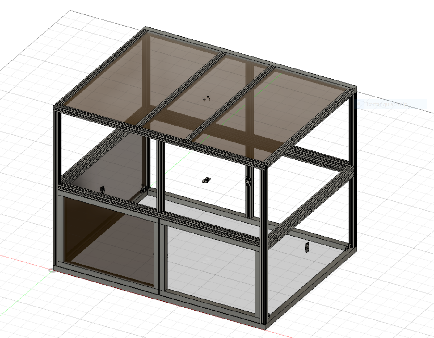
My first task was to design and build an enclosure for the machine, so that it could be used safely by myself and future coops. The design was completed in Fusion 360, and then DXF files were exported in order to cut all of the acrylic sheets on the laser cutter. All of the aluminum extrusion was cut to size using the horizontal bandsaw in the student machine shop. 3-way corner connecting pieces were 3D-printed in PLA, and the door hinges were ordered from McMaster-Carr.
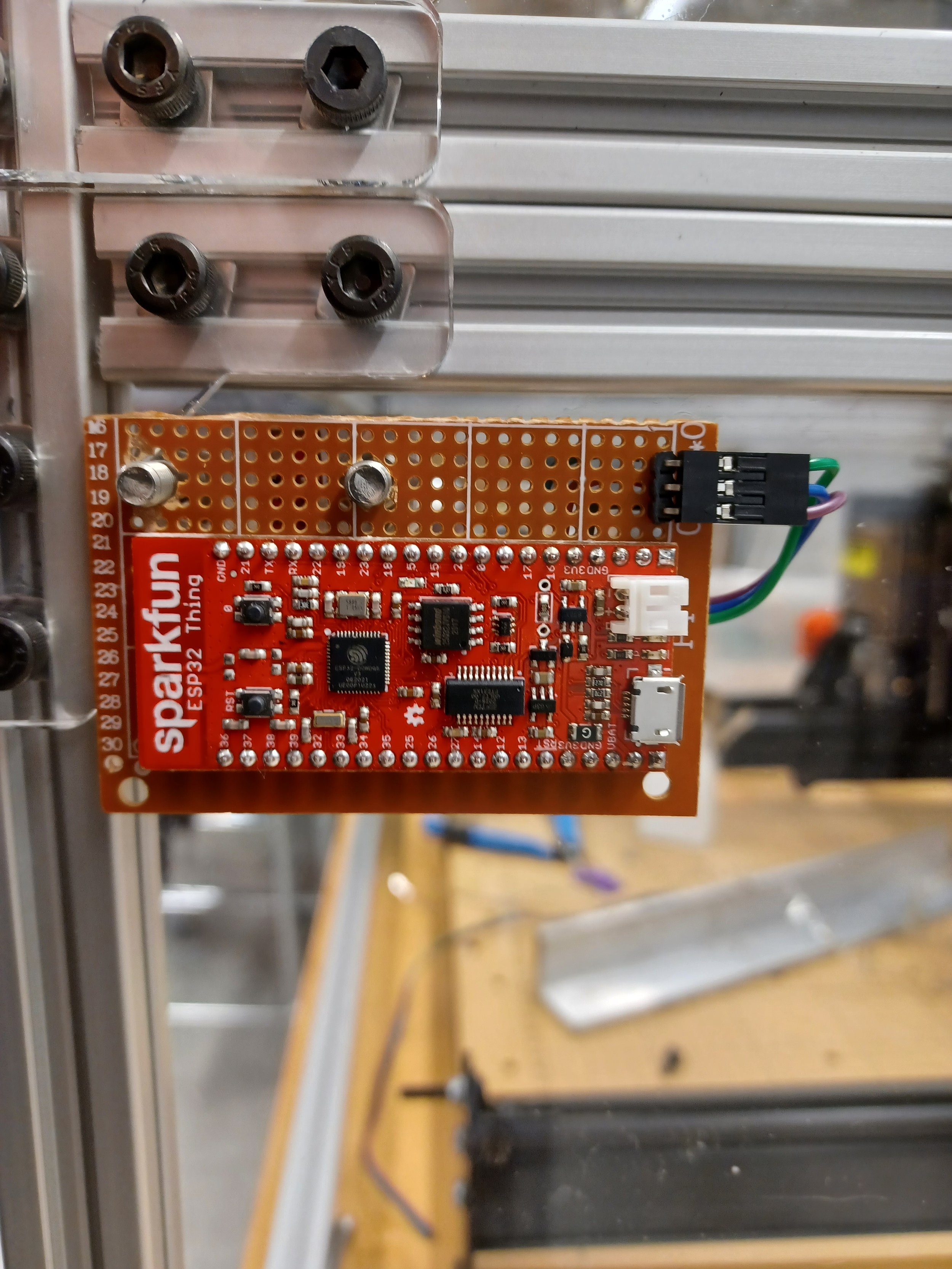
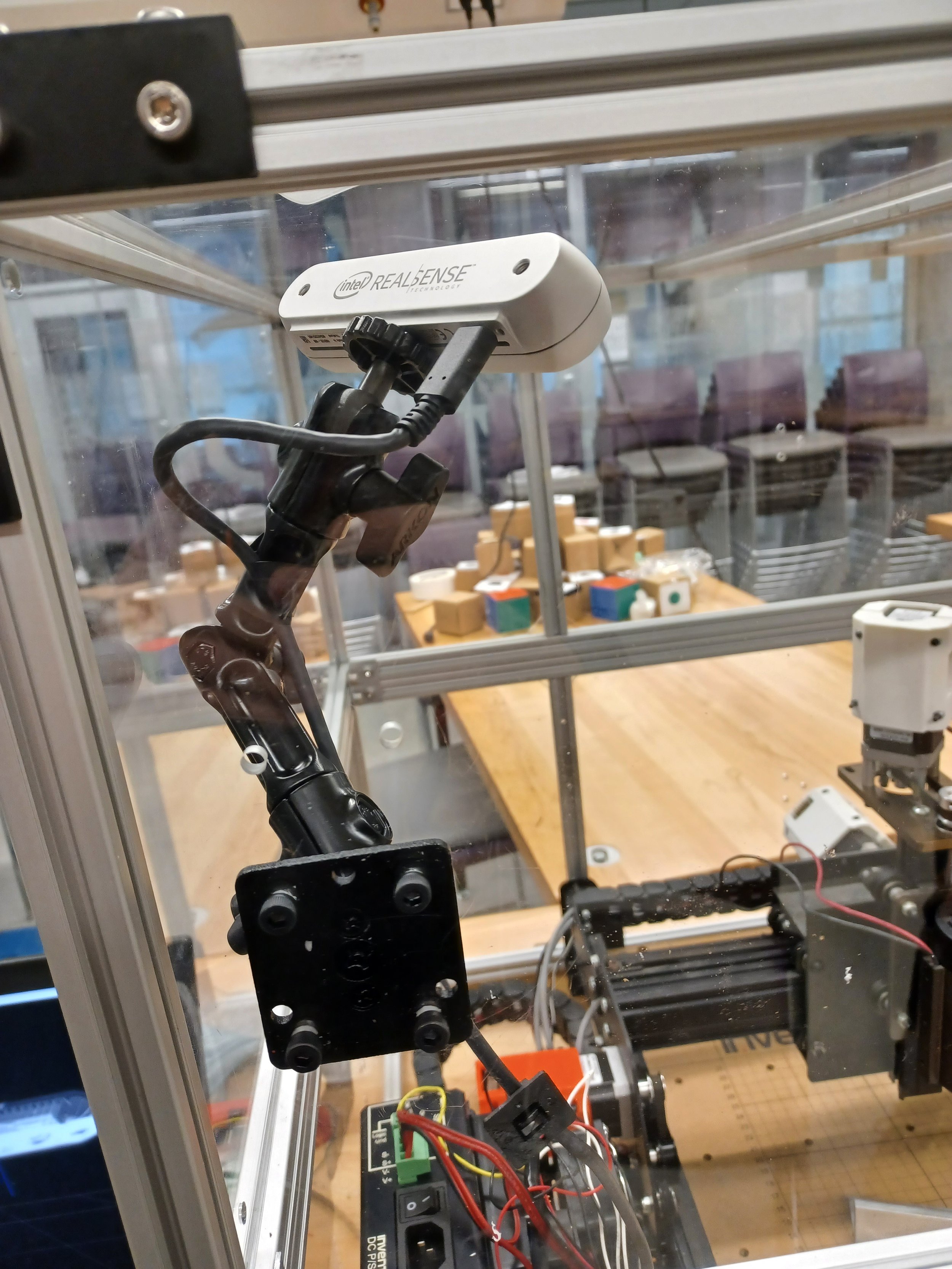
I included a hole pattern at large number of strategic locations on the enclosure to allow for the mounting of a 3d-printed mount that would hold the microphone modules that would be used for audio vibration sensing. Each microphone module was matched with an ESP32 microcontroller, which would handle the capturing of audio data, as well as transmission to the host computer of serial or WiFi. Later on, a hole pattern was added to allow the installation of a camera mount, to facilitate the placement of the 3D camera.
On the machine itself, a high precision rotary encoder was mounted to the shaft of each stepper motor to measure the machine’s motion. This was accomplished by designing and 3D-printing a shaft coupler to interface the 5mm motor shaft with the 1/4” encoder shaft, and a custom mount that would support the encoder behind each stepper motor.
The spindle motor would be fitted with both an accelerometer and a magnetic encoder in order to measure the forces experienced during a machine operation, as well as the changes in RPM. I designed a clever mount that would replace the vent at the back of the motor shroud, with slots that would allow for the installation of the accelerometer and the encoder boards, with a hole centered over the spindle shaft so that the magnetic field could pass freely to the encoder.
All of the encoders, as well as the accelerometer were connected to the same ESP32 microcontroller, necessitating only a single USB cable for those signals.
Much of my time over the work term was spent on software. Initially the plan was to have each microcontroller communicate over WiFi to the host computer, but this ended up not possible for much of the term due to network limitations of the space we were working in. Therefore, for most of the development process, communications would take place over a USB-serial connection to each microcontroller at the highest possible baudrate.
Initially, the goal was to perform a fourier transform on the audio data before transmitting it to the host computer. I was able to implement this successfully using the arduinoFFT library, but ultimately this approach was abandoned to allow for more flexibility in the post-processing of the data.
On the host computer, a python script was created that would handle several important tasks. A serial port for each microcontroller would be opened, and then data would be continuously read from each port. The data, using a simple string encoding convention, could then be parsed and saved to a seperate CSV file for each sensor. The data would also be displayed in real time on several data plots created using the pyqtgraph library. Provided with a simulated toolpath, the script would also plot the projected tool positions over the course of the machine operations, and show a data point for the current tool position trace over the path as the machine moved.
The script also could start and stop the machine operation automatically, provided that the machine controller software was running on the same network.